
Han Jiang Tools Co., Ltd. He Feng
 Compressor wheel groove type line (b) Rotor turbine wheel groove type line")
Figure 1 (a) Compressor wheel groove type line (b) Rotor turbine wheel groove type line

Figure 2 Rotor turbine wheel and broaching machine
Broach Design
Based on the technical requirements for the wheel groove, the compressor wheel groove is simpler than the rotor turbine wheel groove. This section mainly focuses on the design of the rotor turbine wheel groove. The groove type line includes a working surface, non-working surface, and an arc. The contour accuracy of the working surface is 0.007mm, which accounts for cumulative errors in profile, pitch, and tooth angle. The non-working surface and arc have a tolerance of 0.07mm.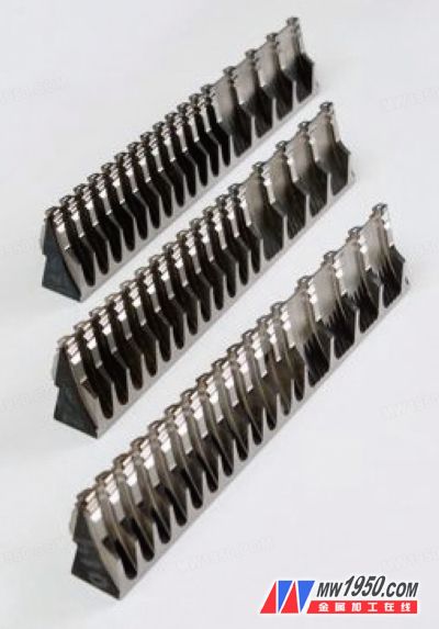
Image 3
Broach Usage
Before installation, it's crucial to inspect the edges of each broaching section for any damage or chipping. Also, check the surface of the broach for scratches or pulls. If any issues are found, they must be addressed before installation. All locating surfaces of the coarse, semi-finished, and fine broaches must be cleaned thoroughly before installation. When installing the broach, place it in a constant temperature workshop for at least two hours. Once the temperature of the broach, machine, and workpiece stabilizes, proceed with installation. Otherwise, thermal deformation may occur. Install the broach according to its sequence number and position, ensuring no misalignment. Secure the broach tightly using a torque wrench to maintain consistent pressure across all sections. A test piece should also be prepared and thermostated before use. It must be clean and securely clamped. Ensure the positioning end face is perpendicular to the broach’s movement direction to avoid skewing during testing. Testing is usually done using a coordinate measuring machine. The benchmarks must match, and the inspection items include linear dimensions, arc tolerances, and surface roughness. After passing the test, the broach can be used for actual production. During the broaching process, monitor the machine’s performance carefully. If the power consumption is too high or unusual vibrations or noises occur, stop the machine immediately and check the broach and equipment before resuming. Metal processing news: Grinding of Gas Turbine Wheel Groove BroachesHigh Speed Door Motor And Control Box
Our company have German SEW Motor, Japan Mitsubishi Controller. Our own brand Hofic servo motor and controller. Chinese famous brand SEJ motor and Holip controller.
About our German SEW Motor and Japan Mitsubishi Controller: It is easy to find the ideal energy-efficient motor for your application at SEW. The series has a suitable design in its range for the globally applicable efficiency classes. Select the power and frequency within this motor design and you have already taken care of the most important selection criteria.All other motor options are of course available independently of the efficiency class. A comprehensive braking concept and cost-optimised built-in encoders ultimately complement the motor range. Comprehensive braking concept and combinations i.e. up to three different brake sizes per motor size featured in the range: Cost-optimised built-in encoders integrated into the motor. Motors for efficiency classes IE1 to IE4.Compact design saves space and costs. Future-proof, also as regards environmental protection (standards). Reduction in operating costs when using energy-efficient motors; our energy-efficient motors conform to the efficiency classes.
About servo High Speed Door Servo Control System: Our rolling gate servo control system is suitable for high speed and high usage soft and hard rolling gate. The whole system is in a small and light package, it has high torque and high operating speed, lower noise, high reliability, smooth and soft operating curves, it`s suitable for high speed and usage environment. The rolling curtain can be controlled by pull switch, push button, Bluetooth, ground radar, ground magnetic sensors. Operating Speed: 1M/s; Operating Width: <16 ㎡; Daily operating time: >2000 time; Rated voltage: 220v; Rated Output: 0.75 KW/1.5KW.
The system can operated via: 1) control box; 2) inching electronic control; 3) continuous automatic operation; 4) emergency stop; 5) single side operation box; 6) time delay; 7) ground radar and/or magnetic sensors. Please refer to Wiring Terminal for eternal connections.
System has fuse/safety wire shutdown switch for three-phase power protection, fuse/safety wire for operating circuit protection, and temperature sensing relay for motor protection.
Stroke Controller utilizes absolute value encoder. Connect the absolute value encoder and reducer via encoder`s axle, and fix the wings on to the reducer, than insert the aviation plug into plug receptacle.
The mounting screw for the control box must inspect regularly to prevent screw been getting loose and falling off. Check the internal and external wirings. Check and change the oil for the redactor on regular basis.
Precision: The system use Full closed-loop servo control and Double Encoder design. This is to ensure long operating life and to prevent overshooting during operating.
Stability: The system utilizes integrated design concept, in order to simplify internal wiring and prevent any function caused by wiring and terminal connections.
High Speed: Motor max speed is 2500 rpm; door max operating speed is 2 m/s.
Smooth: The torque servo system can adjust torque to the load automatically, and its speed curve mode step less speed regulating to ensure a smooth operation.
About SEJ motor and Holip controller: Three-phase asynchronous motor with magnetic brake has broad uses, It is suitable for various mechanical main drive and auxiliary drive, and it is also used for various required rapid stopping and correct positioning. The braking time within 0.2 second. Electric motor is added the DZM series direct current electromagnetic arrester by the basic series(Y series) electric motor.The protection class of electric motor part is IP44,the arrester part is IP23.if be applicable to bad environment can also make the arrester part into IP44,but customer have to put forward a special request while ordering,the manufactory can design a manufacturing exclusively. Its structure diagram is picture 1 and 2,picture 1 is the structure with hand release.Picture 2 is the structure without the hand release.Its operating principle BE, after being to make the retardation coil(6)to connect direct current power supply,because of the function of electromagnetic force,electromagnet(7)attract gag bit(5),and compress spring(24),make arrester disc(2)away from the friction surface of the gag bit(5)and shield(26)(the electrical motor can immediately operate normally).When the power supply cuts off after,the electromagnet(7)loses electromagnet force,the spring(24)releases the gag bit(5)and compress tightly to arrester disc(2),the arrester function,stop(the motor shaft)quickly,make electric motor shop turning to move,for the second time connect power supply will repeat above-mentioned action.
High Speed Door Motor And Control Box,High Speed Door Motor,High Speed Door Servo Motor,Variable-Frequency Servo Motor
Shenzhen Hongfa Automatic Door Co., Ltd. , https://www.hongfadoor.com