1. Overview of FANUC PICTURE Software Features
FANUC PICTURE is suitable for a variety of FANUC systems. Its development environment is Visual Basic, its own integrated compiling and linking functions, strong graphics display and mapping functions, and script editing functions (version 2.7 and above) and simple calculation functions. Works seamlessly with macro compilers or C-executors. If complex calculations are not required, FP software is the ideal software for FANUC interface development; you can choose to use C language actuators to meet complex computing needs.
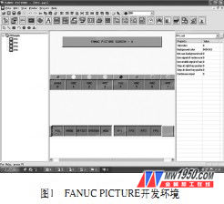
The development environment is on a general-purpose PC, and the operating system is Windows 2000/XP. Load the FANUC PICTURE software onto the PC and develop the required HMI interface. After compiling, the executable file will be transferred to the CNC Flash ROM through the PCMCIA card and run in the CNC. After the CNC restarts, the user-developed interface will be displayed. The display used by the CNC can be either a touch screen or a non-touch screen, as shown in Figure 1.
2. FANUC PICTURE software design process
After the open environment is configured, the HMI interface development work can be performed. The development process is as follows:
(1) First create a new project, enter the file name (such as tes t), select the save path, the project property setting interface will pop up, and set as needed.
(2) Add the main screen, note that there must be a screen structure definition control in each main screen and pop-up screen. It mainly has two functions. One is to set the relationship between the main picture and the sub-picture. The other is to set the pop-up screen. Since this control is not displayed on the CNC screen, it is usually placed in the upper left corner of the screen. This control is not required in the sprite. If there are sub-pictures and pop-up pictures, you need to modify them accordingly. The specific method is described later.
(3) Add a sub-screen. Note that in order to associate with the main screen, you need to make the necessary settings in the "Screen Structure Definition Control" of the main screen, and set the sub-screen name included in the main screen in the sub screen option.
(4) Add pop-up screen, there must be screen structure definition control in this screen, there are two functions, one is to determine the pop-up screen position, that is, the scope of the control box; the second is to set the pop-up screen function .
(5) Save the above screen and add controls to the screen as needed to achieve the required functions. For the use of the controls, refer to the FANUC PICTURE operation manual.
(6) Compile the project, the first time to generate two FPF0FPDT.mem ​​and BY27.mem, the user data is stored in the front, and the system information is followed. Among them, the following files are not in the CNC system. After copying to the machine, you can copy only the previous files. Note that if you simulate the test on the NC guide environment, the file name can only be used with FPF0FPDT.mem.
FANUC provides a professional simulator NC guide. If you want to test the interface created by FP software on it, you need to make the following settings:
There are 5 execution files in the NC guide directory. First, open the list of machine composition setting and make the necessary settings, such as CNC system type, PMC system type, number of axes, number of spindles, etc.
Then open the option setting, set the CNC related parameters, check the fanuc picture function under the CNC, and select the 6M user software capacity.
At this point, the CNC has FP function, and then how to view the screen in the NC guide environment.
First, in the FP installation disk, there are six files cex1~cex6 in F P_n cgp\ f p30, and copy them to the fanuc\NC guide FS31i-A\Machine Setting\1path-3axis-M path.
Then, copy FPF0FPDT.memk to the f anuc\NC guide FS31i-A\Machine Setting\1path-3axis-M\from path to start the simulation environment and view the edited screen. Note that if you simulate the test on the NC guide environment, the file name can only be used with FPF0FPDT.mem. If you write to the NC, the name is variable.
The process of applying FANUC PICTURE production interface is shown in Figure 2.
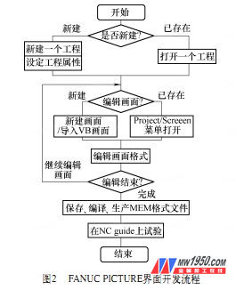
The FANUC PICTURE compilation is used to generate the execution program, input to the CNC side via the memory card, and finally debugged on the machine.
3. Communication interface between interface and CNC (FP function)
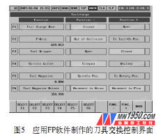
After the graphic editing of the screen is completed, in order to exchange information (read, write, operate and display) with the CNC system, each graphic element must be given a function corresponding to various information of the CNC. For this purpose, FANUC P ICTURE has designed a function instruction library. There are two kinds of instruction libraries: CNC window library and PMC CNC windows library, as shown in Figure 3 and Figure 4.
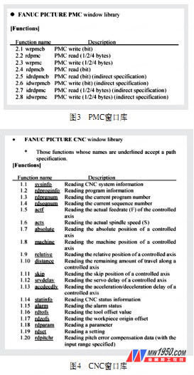
Only some of the instructions are listed here. These instructions are actually the interface between the graphic elements drawn by each control and the CNC information or PMC program using FP (FANUC PICTURE) software. Click on the attribute of the graphic element while drawing, and assign the corresponding function to the element in the attribute item to complete the link to the CNC. For the FP function, refer to the FANUC PICTURE Operating Instructions or the FANUC PICTURE help documentation.
The FP function can be set in the Control Properties dialog box of the FANUC PICTURE software, which is simple to implement and has a huge function.
4. Application examples developed by FANUC PICTURE
According to the customer's own application needs, the tool exchange function interface developed by FANUC PICTURE software is used, and the PMC signal is read and written by the FP library function function. The tool exchange can be performed intuitively through image mode, and the signal state at the time of tool change can be detected at the same time. For easy debugging and operation, as shown in Figure 5.
5 Conclusion
Contemporary CNC machine tools are developing in the direction of high speed, high precision, intelligence, multi-function and high reliability. The good man-machine interface is simple, effective, and has a guiding function, which makes the user feel happy and enhances the interest, thereby improving the use efficiency. Therefore, the man-machine interface design of CNC machine tools directly affects its work efficiency and operational comfort.
FANUC PICTURE software is a tool provided by FANUC for designers to develop human-machine interfaces. Designers can design flexible and diverse applications based on user needs. Therefore, it has a wide application space in special machine tools and special control systems, which opens up a new path for the development of the machine tool industry.
Soft Fridge Magnet,Fridge Magnet,Promotional Gift
Maghard Flexible Magnet Co., Ltd. , http://www.dg-magnet.com