1 Scope
The technical specifications of this certification stipulate the terminology for the acceptance of grid-connected photovoltaic power generation system projects, the composition of the grid-connected photovoltaic power generation system, the contents of inspections and tests, the inspection of the engineering system documentation and contract conformity, the inspection of electrical equipment, the inspection of civil works and the structure of supports, Electrical equipment and system test and inspection report.
The technical specifications of this certification apply to ground-based photovoltaic power generation systems connected to low-voltage distribution networks and medium and high-voltage transmission networks, including: ground-based photovoltaic power generation systems with fixed supports and automatic tracking supports, photovoltaic and building integration (BIPV) power generation systems, and photovoltaics. BAPV power generation system and concentrating photovoltaic power generation system.
This specification does not apply to AC (photovoltaic) component systems, or systems that use energy storage devices (such as batteries) or hybrid systems.
2 normative references
The following documents are indispensable for the application of this document. For dated references, only dated versions apply to this document. For undated references, the latest version (including all amendments) applies to this document.
GB 50009-2001 Building Structure Load Specification
GB 50205-2001 Specification for Construction Quality Acceptance of Steel Structure Engineering
GB 50204-2002 Specification for Construction Quality Acceptance of Concrete Structure Engineering
GB 50202-2002 Specification for Construction Quality Acceptance of Foundation Engineering for Buildings
GB 16895 (all parts) electrical installations of buildings
GB/T 20047.1-2006 Photovoltaic (PV) module safety appraisal Part 1: Structure requirements
GB/T 20513-2006 Guidelines for performance monitoring, data exchange and analysis of photovoltaic systems
GB/T 18216 (all parts) Electrical safety for low voltage distribution systems up to 1000 V ac and 1500 V DC - Test, measurement or monitoring equipment for protective measures
GB/T 19939 Photovoltaic system grid connection technical requirements
GB/T 20046 Photovoltaic (PV) System Grid Interface Features
IEC 61215:2005 Design and qualification of crystalline silicon photovoltaic modules for use in the ground
IEC 61646:2008 Design and identification of thin-film photovoltaic modules for use on the ground
IEC 62108:2007 Design and identification of concentrator photovoltaic (CPV) components and assemblies
IEC 62446:2009 Basic requirements for documentation, commissioning tests and inspections of grid-connected photovoltaic power generation systems
IEC/TR 60755:2008 General requirements for residual current operation of protective devices
CNCA/CTS0004-2009 Technical requirements and test methods for inverters for low voltage grid-connected photovoltaic power generation up to 400V
3 Terms
3.1 System Electrical Efficiency
The ratio of the output power of the system to the electrical power produced by the PV module under certain conditions.
System efficiency can be calculated by the following formula:
3.2 Verification Verification
Various methods for confirming compliance of electrical facilities with relevant standards.
Note: Includes inspections, tests, and reports.
3.3 Inspection Inspection
Electrical facilities are inspected through various sensing organs to determine if their electrical equipment is properly selected and installed correctly.
3.4 Test Testing
Electrical facilities are tested to prove their effectiveness.
Note: This includes obtaining data through appropriate measuring equipment, ie the data is not obtained by inspection.
3.5 Report Reporting
Record the results of the inspection and test.
3.6 Data Sheet
A basic product description and specifications.
Note: Usually only one or two pages, not a complete product specification.
4 The composition of grid-connected photovoltaic power generation system
The grid-connected photovoltaic system on the low-voltage power distribution side mainly includes the following subsystems:
· Photovoltaic subsystem: includes photovoltaic arrays, supports, foundations, and combiner boxes.
· Power regulators: Including grid-connected inverters and power distribution equipment.
· Grid access unit: including relay protection, energy metering and other equipment.
Master control and monitoring: including data acquisition, on-site display systems, and remote transmission and monitoring systems.
·Supporting equipment: including cables, trunkings, lightning protection grounding devices, etc.
Photovoltaic power plants connected to the medium-voltage and high-voltage power grids mainly include the following subsystems:
· Photovoltaic subsystems: including photovoltaic arrays, supports (tracking and fixing), foundations, and combiner boxes.
· Power Regulators: Including grid-connected inverters, power distribution equipment, etc.
· Grid access system: including booster, relay protection, energy metering equipment, etc.
Master control and monitoring: including data acquisition, on-site display systems, and remote transmission and monitoring systems.
Communication systems: channels, switching equipment, and uninterruptible power supplies. (Mastering and monitoring are inseparable from the communication system)
· Civil engineering facilities: computer rooms, fences, roads, etc.
·Supporting equipment: including cables, trunkings, lightning protection grounding devices, etc.
5 inspection and test content

6 Inspection of engineering system documentation and contract compliance
6.1 Basic Information of the Project
As a general requirement, the following basic system information should be provided.
a) project name;
b) Rated system peak power (kWp DC or kVA AC);
c) Manufacturer, model and quantity of photovoltaic modules;
d) Manufacturer, model and quantity of the inverter;
e) installation date;
f) test run date;
g) customer name;
h) installation site;
i) the design unit of the project;
j) The construction unit of the project.
6.2 Inspection of Project Basic Documents
The basic documents include:
a) project approval documents;
b) For land occupied by waste land, the land permit for the project must be submitted; if combined with the construction, the building installation permit must be submitted;
c) Grid-connected power generation projects are required to submit the documents that the grid companies have agreed to access to the grid. If they enjoy the on-grid tariff, they must submit the power grid companies
Industry purchase and purchase agreement;
d) project contract or project-winning agreement with legal basis;
e) Manufacturers, models and quantities of photovoltaic modules and inverters;
f) system installation and operation date;
g) procurement contract for all equipment of the project;
h) overall project design plan;
i) Technical manuals and maintenance manuals for key components (solar cell modules and grid-connected inverters);
j) test reports and certifications for key components (solar battery modules and grid-connected inverters);
k) Project completion report prepared by the construction unit;
l) The system maintenance manual provided by the construction unit for this project.
6.2.1 System Design and Integration Information
The system should have professional design units and integrated units to design and integrate the system. The information provided is as follows:
a) the name of the system design and integration unit;
b) the contact person of the system design and integration unit;
c) The postal address, telephone number and e-mail address of the system design and integration unit.
6.2.2 Engineering Drawings
6.2.2.1 General requirements
A single-line wiring diagram should be provided. The wiring diagram should be marked with the information contained in the following clauses.
Note: Under normal circumstances, this information should be marked on the single-line wiring diagram. For special cases, especially where the wiring diagram of a large system is not enough, this information can be listed separately in a table.
6.2.2.2 General description of PV array
The drawings should include the following matrix design data:
a) component type;
b) the total number of components;
c) the number of strings;
d) The number of components per string.
6.2.2.3 PV string information
The drawings should include the following PV string information:
a) the size and type of the string cable specification;
b) Specifications (if any), type and voltage/current rating of the string overcurrent protection device;
c) Block the diode type (if any).
6.2.2.4 PV array electrical description
The drawings should include the following array of electrical information:
a) phalanx main cable specifications, dimensions and types;
b) the location of the phalanx junction box (if applicable);
c) DC isolation switch type, location and rating (voltage / current);
d) Type, location and rating (voltage/current) of the square array overcurrent protection device (if applicable).
6.2.2.5 Grounding and Overvoltage Protection
The drawings should include the following grounding and overvoltage protection information:
a) Dimensions and connection points of the detailed information of the ground connection, including the installation of equipotential bonding wires of the detailed square frame;
b) All Lightning Protection (LPS) connected to existing information systems;
c) Details of all installed surge protection (including AC and DC line) equipment, including location, type and rating.
6.2.2.6 AC system
The wiring diagram should include the following AC system information:
a) AC isolation switch position, type and rating;
b) The location, type and rating of the AC overcurrent protection device;
c) The location, type and rating (if fitted) of the leakage protector.
6.2.3 Mechanical Design
The rack system data sheet and design drawings should be provided.
6.2.4 Master Device Technical Specifications
As a basic requirement, the specification should provide the following information about the system components:
a) Specifications for all types of components used in the system - according to IEC 61730-1;
b) Specifications for all types of inverters used in the system
Note: The specifications of other important components of the system should also be considered.
6.2.5 Operation and Maintenance Information
Provide information on operation and maintenance, including at least the following:
a) validated correct system operating procedures;
b) system troubleshooting list;
c) emergency shutdown/isolation procedures;
d) maintenance and cleaning advice (if any);
e) Maintenance documents for photovoltaic arrays;
f) Warranty documents for photovoltaic modules and inverters, including the date of commencement of the warranty and the warranty period;
g) Table of wearing parts.
If the automatic tracking system or concentrating photovoltaic system, at least provide the following documents:
a) verified correct automatic tracking system operating procedures;
b) automatic tracking system troubleshooting list;
c) emergency shutdown/isolation procedures;
d) maintenance and cleaning advice (if any);
e) Automatically track system power usage and maximum daily electricity usage;
f) Automatic tracking system warranty documents, including date of commencement of warranty and warranty period.
6.2.6 Test Results
All testing and debugging data files should be provided.
6.3 Inspection of compliance of power station equipment contract
According to the contract or proposal, check the specifications and quantities of all power station equipment item by item and make detailed records. See Appendix 3 for the record form.
Focus on the following major equipment:
a) Models, specifications, and quantities of photovoltaic modules, strings, and photovoltaic arrays;
b) Model, specification and quantity of photovoltaic string box;
c) Models, specifications and quantities of DC distribution systems;
d) The model, specification and quantity of the inverter;
e) Models, specifications and quantities of AC distribution systems;
f) Models and specifications of step-up transformers and grid access systems;
g) type (track/fix), type and material of the bracket system;
h) Model and function of the power station monitoring system.
7 Electrical Equipment Inspection
7.1 General requirements
During the installation, the subsystems and components of key electrical equipment must be inspected. For existing equipment added or replaced, it is necessary to check whether it complies with the GB/T 16895 standard, and it must not damage the safety performance of the existing equipment.
The first and periodic inspections are required to be completed by professional personnel through professional equipment.
7.2 Component Quality Inspection
7.2.1 General requirements
By visual inspection and sensing organs, the appearance, structure, marking, and safety of electrical equipment are checked to meet the requirements of GB/T 16895.
7.2.2 DC System Inspection
The inspection of the DC system includes at least the following items:
a) Whether the design, description and installation of the DC system meets the requirements of GB/T 16895.6, in particular meeting the requirements of GB/T 16895.32:2008;
b) All DC components can operate continuously under rated conditions, and can work stably under the maximum DC system voltage and maximum DC fault current (open circuit voltage correction value is determined according to the local temperature variation range and the performance of the component itself; according to GB /T 16895.32:2008 specifies that the fault current is 1.25 times the short-circuit current;
c) Use class II or equivalent insulation strength on the DC side (GB/T 16895.32:2008 class safety);
d) The selection and installation of photovoltaic string cables, photovoltaic array cables and photovoltaic DC main cables should minimize the risk of grounding and short circuit (GB/T 16895.32:2008);
e) The selection and installation requirements of the wiring system can resist the influence of external factors such as wind speed, ice cover, temperature and solar radiation (GB/T 16895.32:2008);
f) For systems without overcurrent protection devices: The reverse current rating of the module (Ir) should be greater than the possible reverse current, and the same string cable current carrying capacity should be matched with the maximum fault current sum of the parallel module;
g) If a system for overcurrent protection device is installed: the consistency of the overcurrent protection device of the string should be checked, and the correctness and detailedness of the manufacturing instructions should be checked according to GB/T 16895.32:2008 protection instructions for photovoltaic modules;
h) whether the parameters of the DC isolation switch are matched with the inverter on the DC side (GB/T 16895.32:2008);
i) The reverse rated voltage of the blocking diode is at least twice the open-circuit voltage of the photovoltaic string (GB/T 16895.32:2008);
j) If there is a grounding in the DC wire, confirm the separation device installed on the DC side and the AC side to avoid corrosion of electrical equipment.
Note 1: Checking the DC system requires a maximum system voltage and current.
The maximum system voltage is based on the string/matrix design. The open circuit voltage (Voc) of the module is related to the temperature coefficient of the voltage and changes in the illumination radiation.
The maximum fault current is based on the string/matrix design. The short-circuit current (Isc) of the component is related to the temperature coefficient of the current and changes in the radiation radiation (GB/T 16895.32:2008).
Note 2: Component manufacturers generally do not provide component reverse current rating (Ir) value, which is considered to be 1.35 times the rated overcurrent protection of the component.
Note 3: The rated overcurrent protection value of the component is provided by the manufacturer according to IEC 61730-1.
7.2.2.1 Solar PV Module Inspection
The inspection of solar PV modules should include the following items:
a) PV modules must use products that have passed product quality certification in accordance with the requirements of IEC 61215, IEC 61646 or IEC 61730;
b) Materials and components should be selected in accordance with the corresponding drawings and process requirements of the product, and after routine testing, quality control and product acceptance procedures;
c) The component products shall be complete, and the markings on each solar module shall comply with the requirements of IEC 61215 or IEC 61646, Chapter 4, and mark the rated output power (or current), rated working voltage, open circuit voltage, and short circuit current; There are qualified signs; with the manufacturer's storage, installation and circuit connection instructions;
d) Component interconnection should be in accordance with the square array electrical design;
e) For concentrating photovoltaic power generation systems, concentrator photovoltaic modules must use products that have passed the product quality certification in accordance with the requirements of IEC62108; materials and components should use products that meet the corresponding drawings and process requirements, and undergo routine inspection and quality inspection. Control and product acceptance procedures. The component products shall be complete, and the mark on each concentrating photovoltaic component shall have rated output power (or current), rated operating voltage, open circuit voltage, short-circuit current; qualified signs; with the manufacturer's storage, installation, and circuit connections Instructions.
7.2.2.2 Confluence Box
The confluence box inspection should include the following items:
a) The product quality should be safe and reliable, through the relevant product quality certification;
b) The junction box used outdoors shall adopt a sealed structure, and the design shall meet the requirements for outdoor use;
c) The junction box with metal box should be reliably grounded;
d) The use of insulating polymer materials, the selected materials should have good weather resistance, and attached to the use of material specifications, material certificates and other relevant technical information;
e) The connection terminal design of the combiner box should ensure the reliable connection of the cable, and there should be anti-loose parts. For fasteners that are both conductive and fastened, copper parts should be used;
f) The insulation resistance of each PV branch incoming end and sub-matrix outgoing end, and the connecting terminal and combiner earth end shall not be less than 1MΩ.
7.2.2.3 DC Distribution Cabinet Inspection
In the larger photovoltaic square array system, a DC distribution cabinet should be designed, and a plurality of combiner boxes should be aggregated and output to the grid-connected inverter cabinet. The inspection items should include the following:
a) The degree of protection of the structure of the DC distribution cabinet should be able to meet the requirements of the use environment;
b) The DC power distribution cabinet shall be grounded reliably, and shall have obvious grounding identification and shall be provided with corresponding surge absorption protection devices;
c) The terminal design of the DC distribution cabinet should ensure reliable connection of the cable. There should be anti-loosening parts. For fasteners that are both conductive and fastened, copper materials should be used.
7.2.2.4 Connection Cable Inspection
The connection cable inspection should include the following items:
a) The connecting cables should be weather resistant, UV resistant, flame retardant and other anti-aging cables;
b) The wire diameter of the connecting cable shall meet the requirements of the maximum current through the respective circuit of the square array to reduce the loss of the circuit;
c) The cable and terminal should be connected with the end, and there are anti-oxidation measures, no loose connection fastening.
7.2.3 Shock Protection and Grounding Inspection
Electrical shock protection and grounding inspections should at least include the following:
a) Class B leakage protection: The leakage protector shall be allowed to put into use only after confirming normal operation;
b) In order to minimize the lightning induced voltage attack, it should be possible to reduce the wiring loop area;
c) Photovoltaic square array frames should be grounded for equipotential bonding conductors. The equipotential body should be installed to connect the exposed metal and conductive parts of the electrical device to the grounding body. All accessories and brackets shall be connected to a grounding body with a conductivity of at least the conductivity of the copper conductor with a cross-section of 35 mm2. The grounding shall be treated with anti-corrosion and drop resistance;
d) All combiner boxes, AC-DC power distribution cabinets, grid-connected power conditioner cabinets, and current bridges in the PV grid-connected system should be reliably grounded. The grounding should be treated with anti-corrosion and drop resistance.
7.2.4 AC System Check
The inspection of the AC part of the PV system includes at least the following items:
a) Insulation protection should be provided on the AC side of the inverter;
b) All insulation and switching devices function properly;
c) Inverter protection.
7.2.4.1 Grid-connected inverter check
The inverter is the main equipment of the power station. The quality of the inverter directly affects the operation of the power station. Products that pass the certification should be selected.
7.2.4.2 AC Distribution Cabinet Inspection
AC power distribution cabinets refer to devices that implement AC/AC interfaces and some of the main control and monitoring functions in photovoltaic systems. The selection of AC distribution equipment capacity should match the input power supply equipment and the output power load capacity. The main characteristic parameters of AC power distribution equipment include: nominal voltage, nominal current.
7.2.4.3 Automatic Tracking System Check
The automatic tracking system inspection includes at least the following items:
a) The wires of the automatic tracking system should have protective measures;
b) Automatic tracking system In the event of power failure or control failure, the square array can be manually adjusted to a positive south facing position;
c) Automatic tracking system When the wind speed exceeds the maximum allowable wind speed, the square array can be automatically adjusted to the horizontal direction.
7.2.5 System Operation Check
7.2.5.1 Measurement display
Inverter equipment should have a measurement display of the main operating parameters and an indication of operating status. The parameter measurement accuracy should not be less than 1.5.
The measurement display parameters include at least the DC input voltage, input current, AC output voltage, output current, and power factor; the status indication shows the state of the inverter device (operation, fault, shutdown, etc.).
Display function: The display content is DC current, DC voltage, DC power, AC voltage, AC current, AC frequency, power factor, AC power generation, system power generation, system power generation, air temperature, and solar radiation.
The status display mainly includes the operating status, abnormal status, delisting status, grid-connected operation, emergency operation, and alarm content code.
7.2.5.2 Data Storage and Transmission
The grid-connected photovoltaic power generation system must be equipped with a local data acquisition system that can collect all kinds of operational data of the system and upload it through GPRS/CDMA wireless channels, telephone lines or the Internet public network according to the specified protocol.
7.2.5.3 Transit (straight) current distribution equipment protection function
Cross-current (straight-flow) power distribution equipment should have at least the following protection functions:
a) Output overload and short circuit protection;
b) Overvoltage protection (including lightning protection);
c) Leakage protection function.
7.3 Tags and Labels
Photovoltaic system label and identification inspection includes at least the following items:
a) All circuits, switches and terminal equipment must be affixed with corresponding labels;
b) All DC junction boxes (photovoltaic power generation and photovoltaic junction boxes) must be affixed with a warning label indicating that the photovoltaic phasor junction box contains the source components and is still possible after the photovoltaic inverter and the public power grid are detached. charged;
c) AC main disconnector should have obvious identification;
d) For dual-supply systems, a warning label shall be affixed at the intersection of the two power points;
e) The system single line diagram should be pasted inside the equipment cabinet door;
f) The label of the setting details of the inverter protection shall be affixed in an appropriate position in the inverter room;
g) The emergency shutdown procedure should be pasted in place;
h) All signs and labels must be permanently attached to the device in a suitable form.
8 Civil Engineering and Structure Inspection
8.1 General requirements
The PV subsystem can be designed to meet the average or peak demand of the system's annual power output. The size of the PV subsystem can be determined based on the specific load that needs to be met, or it can be optimized based on a common load range and system performance price ratio. The result is OK.
At a minimum, the following requirements should be met:
a) Civil and support structures should meet the design strength requirements;
b) Civil and support structures should meet the requirements of the local environment;
c) Civil and support structures should meet the requirements of relevant standards.
8.2 square bracket
The square bracket can be fixed or discontinuous/continuously adjustable. The system design should choose the proper orientation for the square array. The optical components should generally face south; in the case of a specific geographical environment to avoid occlusion, consider Adjust the design within ±20° South.
The installation position of the PV array should be avoided to avoid shadowing of other buildings or trees. There should be enough space between the arrays to ensure that the PV arrays do not block each other.
The best choice for the installation angle of fixed arrays depends on many factors such as: geographical location, annual solar radiation distribution, direct radiation and scattered radiation ratio, load power requirements and specific site conditions.
The design of the support structure of the phalanx should comprehensively consider the geographical environment, wind load, the status of the phalanx field, the specifications of the photovoltaic modules, etc. to ensure the firmness, safety, and reliability of the photovoltaic phalanx.
Photovoltaic subsystems can be installed in many forms, such as ground, roof, and building integration. The installation form of the roof and building integration shall consider the bearing surface load capacity, and the engineering design shall comply with the relevant building standard requirements.
The ground-mounted PV array bracket should adopt steel structure. The bracket design should ensure that the PV module and the bracket are connected firmly and reliably. The base and the foundation are firmly connected. The module should not be less than 0.6m away from the ground. Considering the site environment and weather conditions, it may be appropriate. Adjustment.
The square bracket steel structure should be treated with anti-rust coating to meet the long-term outdoor use requirements. Photovoltaic modules and square array fasteners should be made of stainless steel or surface-coated metal parts or other anti-corrosion materials with sufficient strength.
Steel frame brackets should follow the “Code for acceptance of construction quality of steel structures†(GB 50205-2001)
8.3 Basics
For installation on the ground square base should meet the requirements of GB 50202-2002.
For the foundation installed on the roof of a building, in addition to meeting the requirements of GB 50202-2002, the relevant requirements of GB 50009-2001 should also be met.
8.4 Photovoltaic field requirements
The selection of the square field should avoid the influence of shadows. There should be enough space between the parties to ensure that the solar module receives direct sunlight without shading between 9 am and 3 pm in the winter solstice.
For photovoltaic systems installed on the ground, the field surface shall be compacted and the loose soil shall be reinforced. For areas with an annual precipitation above 900mm, drainage facilities shall be provided, and a layer of sand and gravel shall be considered on the compacted surface for reduction. Small mud water splashes.
For photovoltaic systems installed on the ground or on rooftops, the influence of ambient changes on the photovoltaic array should be considered.
The photovoltaic field farm should be equipped with appropriate fire protection facilities.
9 Testing of Electrical Equipment and Systems
9.1 General requirements
Electrical equipment testing must meet the requirements of GB 16895.23-2005-T.
Measuring instruments and monitoring equipment and test methods should refer to the relevant requirements of GB/T 18216. If alternative equipment is used instead, the equipment must achieve the same level of performance and safety.
If a failure occurs during the test, you need to re-test each item before it.
When appropriate, item-by-item tests should be performed in the following order:
a) AC circuit testing must meet the requirements of GB 16895.23-2005-T;
b) Test for connection and matching of protection devices and equipotential bodies;
c) polarity test;
d) string open circuit voltage test;
e) string short-circuit current test;
f) functional test;
g) Test of the DC resistance of the insulation circuit.
The IV characteristic curves of photovoltaic modules connected in series and in parallel according to a certain method should have good consistency to reduce the loss of combination of square arrays; the combined loss of optimized PV subsystem design should not exceed 8%. (Based on criteria)
9.2 Tests for Protective Devices and Equipotentials
Protection or couplings should be reliably connected.
9.3 Polarity Test
Check the polarity of all DC cables and indicate the polarity to ensure that the cables are connected correctly.
Note: For safety reasons and prevention of equipment damage, polarity tests should be conducted before other tests and switch closure or string overcurrent protection device access.
The open circuit voltage of each photovoltaic string should be measured. Prior to open circuit voltage measurement, all switches and overcurrent protection devices (such as installation) should be turned off.
The measured value should be compared with the expected value, and the result of the comparison should be taken as the basis for checking whether the installation is correct. For multiple identical string systems, the voltages between strings should be compared under stable lighting conditions. The string voltage values ​​should be equal under stable light conditions (in a stable light condition, should be within 5% range). For unsteady lighting conditions, the following can be used
method:
a) Extend the test time;
b) using multiple meters, one measuring a photovoltaic string;
c) Use an irradiation meter to calibrate the readings.
Note: Test voltage values ​​below the expected value may indicate that one or more components have incorrect polarity connections, or have low insulation levels, or that the conduits and junction boxes are damaged or have accumulated water; higher than expected values ​​and have a large difference is usually Due to wiring error.
9.4 Test of PV string current
9.4.1 General requirements
The purpose of the photovoltaic string current test is to verify that the wiring of the photovoltaic array is correct. This test is not used to measure the performance of the photovoltaic string/array.
9.4.2 Test of Short-Circuit Current in PV Strings
Use appropriate test equipment to measure the short-circuit current of each string. The test of the short-circuit current of the string is related to the test procedure and the potential danger. It should be carried out with the following test steps.
The measured value must be compared with the expected value. For multiple identical string systems and under stable lighting conditions, the currents between individual strings should be compared. The string short-circuit current values ​​should be the same under steady light conditions (in a stable light condition, should be within 5 %).
For unsteady lighting conditions, the following methods can be used:
a) Extend the test time;
b) multiple meters can be used, one measuring a photovoltaic string;
c) Use an irradiation meter to calibrate the current reading.
9.4.2.1 Short Circuit Current Test Procedure
a) Ensure that all PV strings are independent of each other and all switchgears and isolators are disconnected;
b) The short-circuit current can be measured with a clamp ammeter and a coaxial ammeter.
9.4.3 PV string test
The measured value must be compared with the expected value. For multiple systems of the same string, each string should be compared separately under steady light radiation conditions. The string current values ​​should be the same (in the case of stable lighting, should be within 5%).
For unsteady lighting conditions, the following methods can be used:
a) Extend the test time;
b) test using multiple meters, one meter measuring a photovoltaic string;
c) Use an irradiation meter to calibrate the current reading.
9.5 Functional Test
Functional tests follow these steps:
a) Both switchgear and control equipment should be tested to ensure the normal operation of the system;
b) The inverter should be tested to ensure the normal operation of the system. The testing process should be provided by the inverter supplier;
c) The grid fault test procedure is as follows: AC main circuit disconnector is disconnected - the photovoltaic system should immediately stop operating. After this, the AC isolation switch should be reclosed to return the PV system to normal operation.
Note: The grid fault test can be corrected under steady light conditions. In this case, the load is matched as closely as possible to the actual power provided by the PV system before the AC disconnector is closed.
9.6 Photovoltaic Array Insulation Resistance Test
9.6.1 General Requirements
Photovoltaic arrays should be tested as follows:
a) Limit unauthorised personnel from entering the work area during testing;
b) Do not touch the electrical equipment directly by hand to prevent electric shock.
c) The insulation test device shall have the ability to automatically discharge;
d) Appropriate personal protective clothing/equipment should be worn during testing.
Note: For some system installations, such as large-scale system insulation installation accidents or suspecting that the equipment has manufacturing defects or doubts about the dry test results, we can properly test the wet squares. The test procedure refers to ASTM Std E 2047.
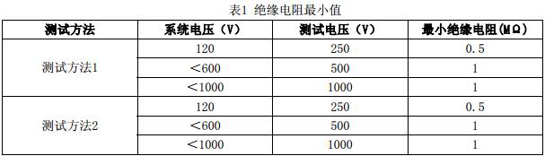
9.6.2 Test Methods
9.6.2.1 The following two test methods can be used:
a) Test method 1 - First test the insulation resistance of the square negative electrode to ground, and then test the insulation resistance of the square positive electrode to ground.
b) Test Method 2—Test the insulation resistance to ground when the positive and negative poles of the photovoltaic array are short-circuited.
9.6.2.2 For systems with no square grounded frame (if type II insulation is available), the following two tests can be selected:
a) Insulation test between cable and earth.
b) Insulation test between the square array cable and the assembly frame.
9.6.2.3 For conductive parts that are not grounded (eg rooftop photovoltaic tiles) insulation tests shall be conducted between the square array cable and the grounding body.
Note 1: Where test method 2 of 9.6.2.1 b) is used, arc discharge should be minimized and the positive and negative electrodes of the square array should be short-circuited in a safe manner.
Note 2: The specified test procedure ensures that the peak voltage cannot exceed the component or cable rating.
9.6.3 Test Procedure
Before starting the test: unauthorized persons are prohibited from entering the test area and the electrical connection from the inverter to the photovoltaic array must be disconnected.
9.6.2.1 b) In Test Method 2, if a short-circuit switch box is used, the square-array cable shall be safely connected to the short-circuit switch device before the short-circuit switch is closed.
Use an appropriate method for insulation resistance testing and measure the insulation resistance between the ground and the square array cable. See Table 1 for details.
Make sure the test is safe before doing any tests.
Ensure that the system power supply has been cut off before testing the cable or touching any live conductor.
9.7 PV array nominal power test
The field power can be measured using the "solar cell square array tester" calibrated by a third-party testing unit to measure the IV characteristic curve of the solar cell branch, and the sampling rate should not be less than 30%. From the IV characteristic curve, the maximum output power of the branch can be obtained. In order to convert the maximum output power obtained by the test to the peak power, the following corrections of items a), b), c) and e) are required.
If there is no "solar cell square array tester", the actual DC output power of the power station can also be obtained by field testing the operating voltage and operating current on the DC side of the power station. In order to convert the actual output power of the power station obtained by the test to the peak power, all the following items need to be corrected.
The following six corrections should be made after testing to ensure fairness:
a) Light intensity correction:
In the non-standard conditions, the light intensity correction should be performed and the light intensity corrected according to the linear method.
b) Temperature correction:
The junction temperature is generally estimated to be 60°C, and for every 1°C increase above 25°C, the power is reduced by 2/1000 (crystalline silicon is
Five-thousandths of a thousandths of total), the total dropped 7%.
c) Combination loss correction:
After the solar cell modules are connected in series and in parallel, there will be a combination loss, and the combined loss correction should be performed. The combined loss of solar cells should be controlled within 5%.
d) Maximum power point correction:
It is difficult for the solar cell to work at the maximum power point under working conditions and it needs to be compared with the power curve for correction; this correction may not be made for a system with a solar maximum power point tracking (MPPT) device;
e) Solar cell orientation correction:
Different solar cell orientations have different power outputs and power losses. If there are different orientations of solar cells that are connected to the same inverter, this calibration is required.
9.8 Power Quality Test
1) First disconnect the photovoltaic power plant from the power grid and test the power quality of the power grid:
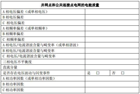
2) Connect the inverter to the grid and test the power quality of the grid point after it is stable:

Note: During the test, it should be noted that whether the deviation of the power quality parameters is caused by the original deviation of the grid or the deviation generated after the photovoltaic system is connected to the grid. The basis for the determination of the power quality index is implemented according to the requirements of GB/T19939.
9.9 System Electrical Efficiency Test
9.9.1 General Requirements
Photovoltaic system electrical efficiency should be tested in accordance with the following requirements:
a) Limit unauthorised personnel from entering the work area during testing;
b) Do not touch the electrical equipment directly by hand to prevent electric shock.
c) The system electrical efficiency test should be carried out under sunshine intensity greater than 500W/m2;
d) Appropriate personal protective clothing/equipment should be worn during testing.
Note: When the PV module is installed with a certain inclination angle, the sunshine intensity test device should maintain a uniform tilt angle with the module.
9.9.2 Test Methods
Photovoltaic system electrical efficiency should be tested as follows:
a) First measure the current sunlight intensity with a standard solar meter;
b) Measure the AC power at the grid connection point of the grid-connected inverter while measuring the solar radiation intensity;
c) According to the power of the photovoltaic array, the sunshine intensity and the temperature power coefficient, according to the calculation formula, the generation power of the photovoltaic array at that time can be calculated;
d) According to 3.1, the electrical efficiency of the system can be calculated.
9.10 Concentrating Photovoltaic Module Test
For concentrating photovoltaic systems, off-axis spot damage testing of concentrating photovoltaic modules should be performed on the site. See IEC 62108 clause 10.14 for test methods.
9.11 Automatic Tracking System Function Test
For the automatic tracking photovoltaic power generation system and the concentrating photovoltaic power generation system, the site shall be tested for operational function and tracking accuracy.
9.11.1 Action Function Test
Test content includes:
a) Height angle direction manual mode action test
Switch the tracking system to manual operation mode. Adjust the elevation angle in the manual mode with the corresponding mechanism. During the test, the vibration and effective transmission of the relevant organization shall be confirmed, and it shall be confirmed whether the elevation angle operation range meets the range defined in the specifications of the system.
b) Azimuth direction manual mode motion test
Switch the tracking system to manual operation mode. In manual mode, the azimuth is adjusted by the corresponding mechanism.测试过程ä¸é‡ç‚¹ç¡®è®¤ç›¸å…³æœºæž„çš„æŒ¯åŠ¨å’Œæœ‰æ•ˆä¼ åŠ¨ï¼Œå¹¶ç¡®è®¤æ–¹ä½è§’è¿è¡ŒèŒƒå›´æ˜¯å¦æ»¡è¶³è¿½æ—¥ç³»ç»Ÿè§„æ ¼ä¹¦ä¸æ‰€å®šä¹‰çš„范围。
c)独立机械é™ä½æ‰‹åŠ¨æ¨¡å¼åŠ¨ä½œæµ‹è¯•
一般情况下è¦æ±‚追日系统é…置独立的机械é™ä½å•å…ƒã€‚在手动模å¼ä¸‹ï¼Œåˆ†åˆ«æµ‹è¯•é«˜åº¦è§’和方ä½è§’æ–¹å‘上的独立机械é™ä½å•å…ƒçš„工作状æ€ã€‚机械é™ä½å•å…ƒåŠŸèƒ½æ£å¸¸ä¸Žå¦çš„判æ–ä¾æ®æ˜¯ç›¸åº”的过载ä¿æŠ¤è£…置是å¦æ£å¸¸å¯åŠ¨ã€‚
d)自动模å¼åŠ¨ä½œæµ‹è¯•
将系统地点和日期分别设定为当地和设备商需è¦è®¾å®šå½“时对应时间。将追日系统切æ¢è‡³è‡ªåŠ¨å·¥ä½œæ¨¡å¼ã€‚使追日系统è¿è¡Œä¸€æ•´å¤©ï¼Œæµ‹è¯•è¿è¡ŒçŠ¶å†µã€‚
e)通æ–电测试
将系统切æ¢è‡³è‡ªåŠ¨å·¥ä½œæ¨¡å¼ã€‚
在追日系统跟踪时间段内,切æ–主电æº20分钟åŽå†å¼€å¯ä¸»ç”µæºï¼Œæµ‹è¯•è¿½æ—¥ç³»ç»Ÿæ˜¯å¦èƒ½è¿è½¬è‡³æ£ç¡®ä½ç½®ã€‚
在追日系统跟踪时间段内,手动方å¼æ”¹å˜è·Ÿè¸ªå™¨æ–¹ä½è§’和高度角ä½ç½®ï¼Œç„¶åŽåˆ‡æ–主电æº20分钟åŽå†å¼€å¯ä¸»ç”µæºï¼Œæµ‹è¯•è¿½æ—¥ç³»ç»Ÿæ˜¯å¦èƒ½è¿è½¬è‡³æ£ç¡®ä½ç½®ã€‚
9.11.2跟踪精度测试
采用光电二æžç®¡æˆ–CCDç‰æ£€æµ‹ç³»ç»Ÿç›´æŽ¥æµ‹é‡è¿½æ—¥ç³»ç»Ÿç»„件平é¢ç›¸å¯¹äºŽé˜³å…‰å…‰çº¿çš„ä½ç½®å差。
当采用户外自然光æ¥è¿›è¡Œæµ‹è¯•æ—¶ï¼Œç›´æŽ¥æ£å¸¸æ—¥ç…§å¼ºåº¦ä¸åº”低于500W/m2,测试将在追日系统的准确跟踪全范围内进行。连ç»ä¸¤å‘¨çš„最大追日åå·®ä¸å¾—超过±3°。
以上追日精度测试时,考虑组åˆè½½è·ä¸ºç›¸å½“于20m/s 风速情况下的é™æ¢è½½è·ã€‚该é™æ¢è½½è·ä»¥å¤–åŠ è´Ÿè½½å½¢å¼å‡åŒ€çš„安装固定在追日系统上。
10检查报告
10.1一般è¦æ±‚
检测过程完æˆåŽï¼Œåº”æ供检验报告。包括如下内容:
a)系统信æ¯ï¼ˆå称,地å€ç‰ï¼‰ï¼›
b)电路检查和测试清å•ï¼›
c)检查报告;
d)电路的测试结果;
e)检查人员姓ååŠæ—¥æœŸã€‚
检测报告以附录Aä¸ºæ ‡å‡†ã€‚
10.2首次检查
首次检查报告应该包å«è®¾è®¡å•ä½ã€æ–½å·¥å•ä½å’Œæ£€æŸ¥å•ä½çš„相关信æ¯åŠç³»ç»Ÿä¸å„å•å…ƒéƒ¨ä»¶çš„检查和现场检测的报告。
首次检查报告应明确å¤æ£€æ—¶é—´ã€‚å¤æ£€åº”该考虑到设施和设备的类型ã€ä½¿ç”¨å’Œæ“作频率åŠç»´ä¿®è´¨é‡å’Œå…¶ä»–å¤–åœ¨å› ç´ å¯¹ä»–ä»¬çš„å½±å“。
10.3定期检查
æ ¹æ®æœ¬æŠ€æœ¯è§„范第5ç« è¦æ±‚对现有设备进行定期检验,并å‚考之å‰å®šæœŸæ£€éªŒå‘生的问题和建议。
定期检验报告应该包括任何故障和è¦æ±‚ä¿®ç†æˆ–改进的建议(如:系统的å‡çº§ä»¥ç¬¦åˆå½“å‰æ ‡å‡†ï¼‰ã€‚
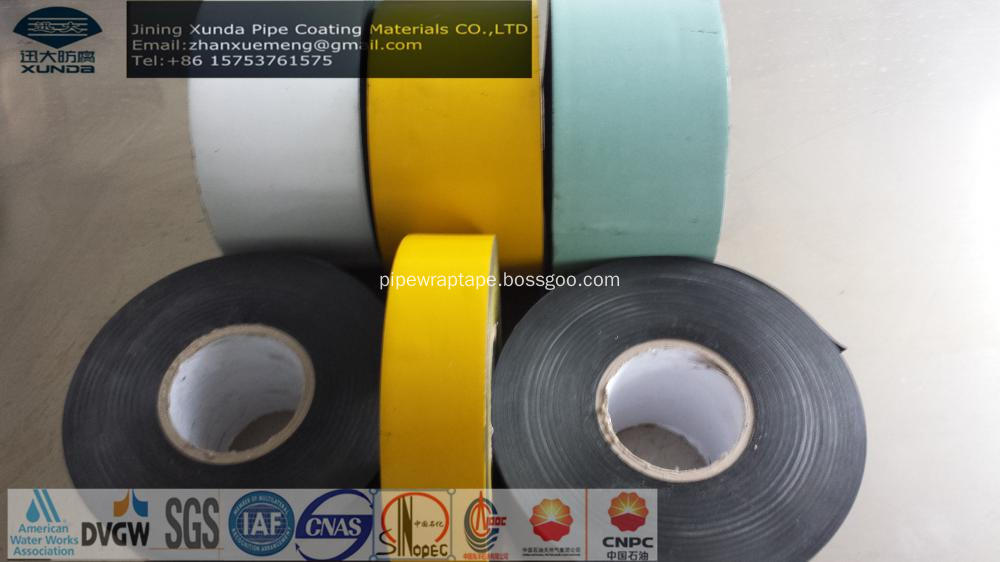
Pipeline Outer Protection Tape
I .Description
Pipeline Outer Protection Tape is Cold applied tape coating system for corrosion protection of Oil, Gas, Petrochemical, and Waste Water underground or overhead pipelines. The outer-layer tape backing shall be compounded so that it will be resistance to outdoor weathering.
The outer-layer tape shall be applied after the inner-layer tape by hand or with a wrapping machine.
II .Structure
The specification of the tape consists of two layers, adhesive layer and film backing
Adhesive: butyl rubber
Outer layer: Special blend of stabilized polyethylene
III. Features:
Excellent adhesion to inner-layer tape and self
Resistant to UV
Can be applied over a wide temperature range
Good conformability and consistent uniform thickness
Easily applied with no special equipment
Compatible with common pipe coatings
Excellent resistance to cathodic disbonding
Meets ASTM D 1000 Standard
Cold applied
â…£.Technical datas:


Pipeline Outer Protection Tape
Metallic Pipe Line Wrap Tape, Pipelines Outer Protection Tape, Pipe Outer Protective Tape, Pipeline Wrap Tape
Jining Xunda Pipe Coating Materials Co.,Ltd , http://www.pipe-wrap.com